Unlocking Electronics: Your Guide to Circuit Symbol Diagrams

Imagine trying to build a complex machine without a blueprint. That’s essentially what designing electronic circuits would be like without a standardized system of symbols. Circuit symbols are the language of electronics, a visual shorthand that allows engineers and hobbyists alike to represent complex electrical components and their connections in a clear and concise manner.
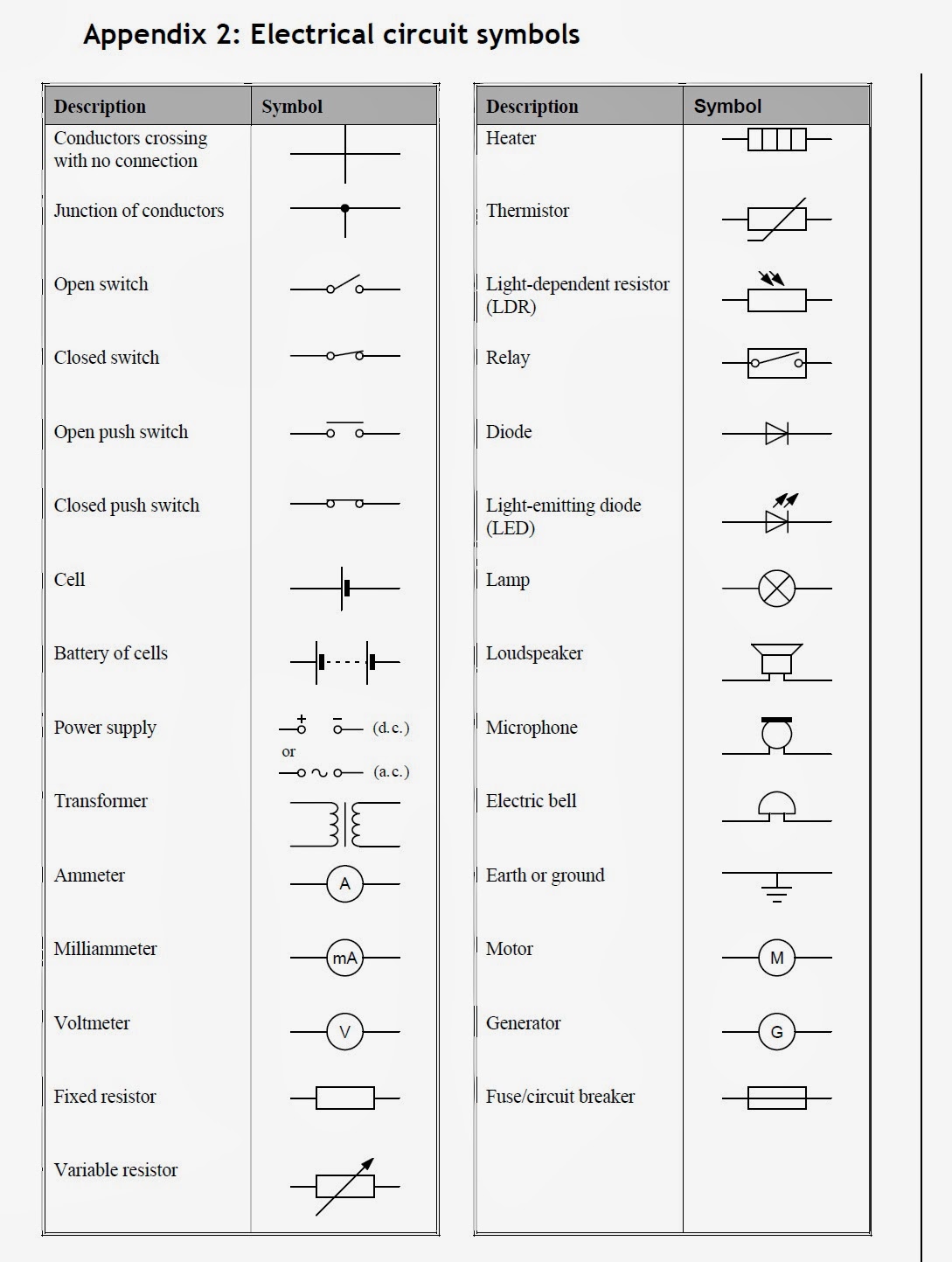
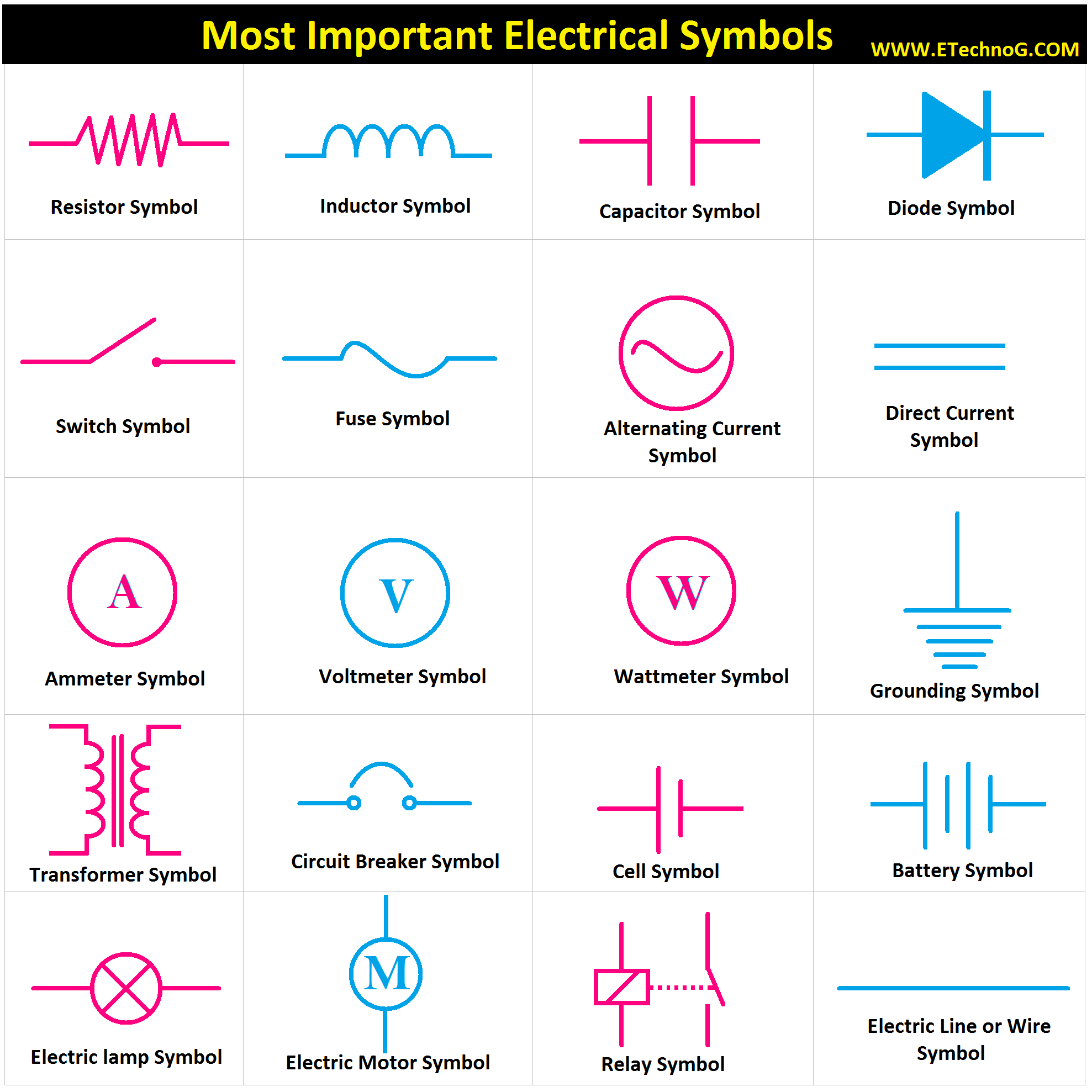
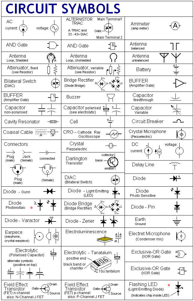
This intricate language, represented by a collection of standardized graphical representations, commonly known as a "list of circuit symbols" or a "circuit symbol diagram," is essential for designing, analyzing, and troubleshooting electronic systems. From simple resistors to complex microcontrollers, each component has its unique symbolic representation, making circuit diagrams universally understandable across different languages and technical backgrounds.
The history of circuit symbols is intertwined with the development of electrical engineering itself. As the field progressed from basic experiments with electricity to complex circuit designs, the need for a standardized system of representation became increasingly evident. Early circuit diagrams were often crude and varied, but over time, a more formalized set of symbols emerged, driven by the need for clear communication and collaboration among engineers. The standardization of these symbols has played a crucial role in the rapid advancement of electronic technology.
The importance of standardized circuit symbols cannot be overstated. They provide a common language that transcends geographical and linguistic boundaries, allowing engineers worldwide to collaborate effectively. Imagine the chaos if every country or company used its own unique set of symbols. Circuit diagrams would become unintelligible, hindering innovation and progress. The standardized list of circuit symbols ensures that everyone working with electronics is speaking the same visual language.
One of the main issues surrounding the use of circuit symbols is ensuring consistent application and understanding. While standardized lists exist, variations in style and interpretation can occasionally lead to confusion, especially in complex designs. This underscores the importance of adhering to established standards and using clear, unambiguous representations in circuit diagrams.
For instance, a resistor is represented by a zigzag line, a capacitor by two parallel lines, and a battery by two parallel lines of unequal length. Understanding these simple representations is the first step to reading and interpreting complex circuit diagrams. More complex components, like transistors and integrated circuits, have more elaborate symbols that reflect their function and internal structure.
One benefit of using standardized circuit symbols is the ease of communication they provide. Engineers can share their designs across the globe without worrying about language barriers. Another advantage is the simplified design process. Using symbols allows engineers to quickly sketch and iterate on their designs without having to draw detailed representations of each component. Finally, circuit symbols are crucial for troubleshooting. By examining a circuit diagram, technicians can quickly identify faulty components and repair malfunctioning circuits.
To effectively use circuit symbols, one can follow a simple action plan. First, familiarize yourself with the standard list of symbols. Several resources, both online and in textbooks, provide comprehensive lists. Then, practice reading and interpreting simple circuit diagrams. Start with basic circuits and gradually move on to more complex ones. Finally, start creating your own circuit diagrams using software or by hand. This will solidify your understanding of the symbols and their practical application.
Advantages and Disadvantages of Standardized Circuit Symbols
| Advantages | Disadvantages |
|---|---|
| Universal understanding | Potential for misinterpretation if not adhering to standards |
| Simplified design process | Requires initial learning and familiarization |
| Efficient troubleshooting | Can become complex for highly integrated circuits |
Five best practices for using circuit symbols include adhering to standardized representations, maintaining consistency in style and orientation, using clear and unambiguous labels, organizing the diagram logically, and ensuring adequate spacing between symbols for readability.
Frequently Asked Questions: What is a resistor symbol? What is a capacitor symbol? What is a diode symbol? What is a transistor symbol? How to read a circuit diagram? Where can I find a list of circuit symbols? How do I use circuit symbols in circuit design software? What are some common mistakes to avoid when using circuit symbols?
In conclusion, the standardized list of circuit symbols is an indispensable tool for anyone working with electronics. It provides a universal language that facilitates communication, simplifies design, and enables efficient troubleshooting. By understanding the history, importance, and practical application of these symbols, you can unlock the full potential of electronic circuit design. Take the time to familiarize yourself with the standard list, practice reading and creating circuit diagrams, and embrace the power of this essential tool. The world of electronics awaits.
Dominate fifa 18 unlocking the top teams
Exploring the allure of forbidden books
Unlocking the power of honda ridgeline imagery


