Understanding Electronic Symbols and Their Purpose
Imagine trying to assemble a complex puzzle without knowing what each piece represents. That's akin to navigating the world of electronics without a firm grasp of electronic symbols and their corresponding functions. These symbols are the language of circuits, providing a visual shorthand for various components and their interconnectedness.
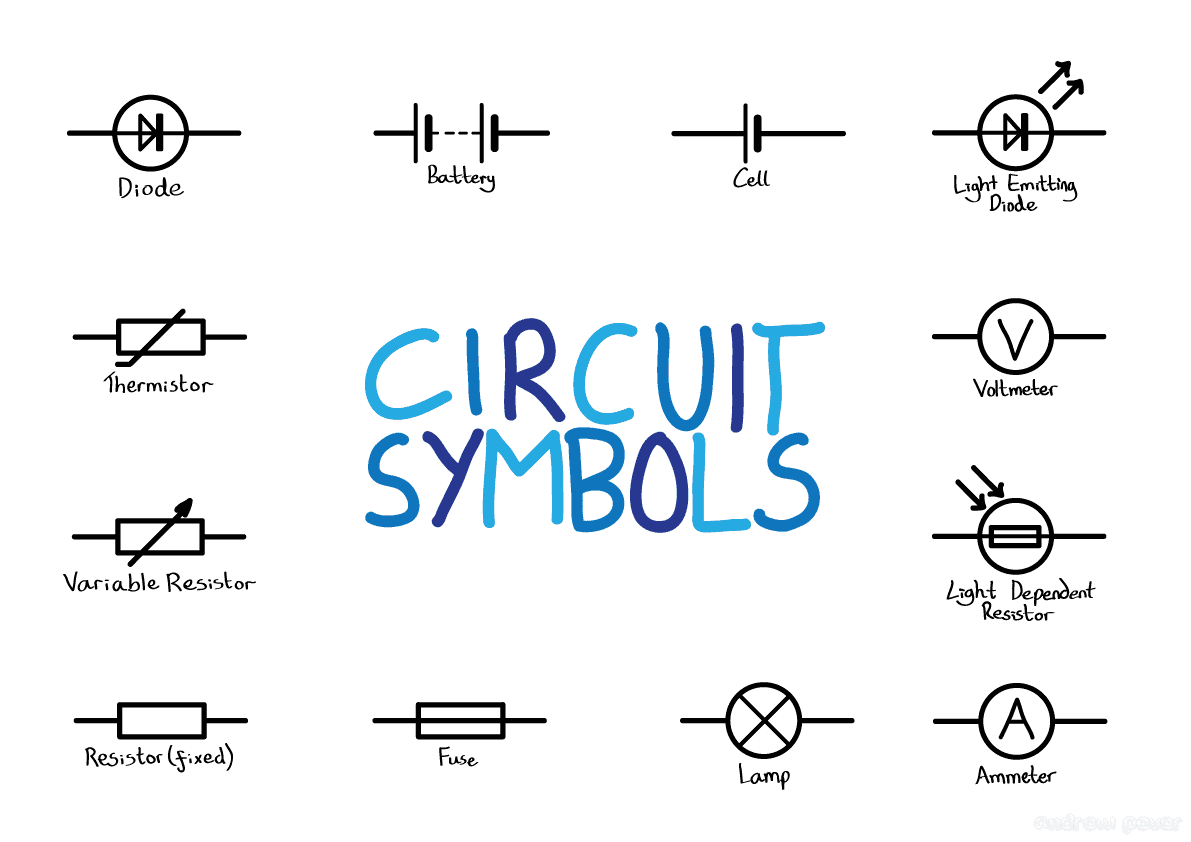
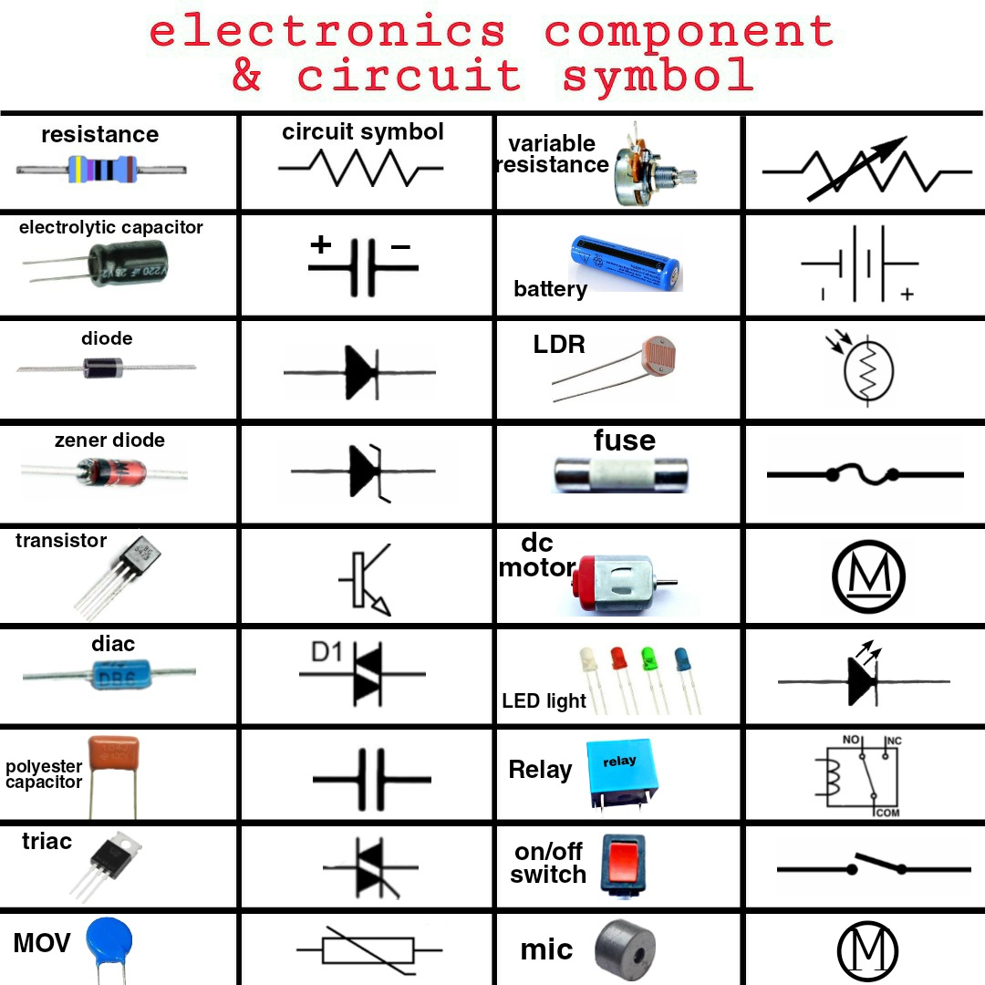
Electronic symbols are standardized graphical representations of electronic components used in circuit diagrams. They simplify complex designs, making them easier to understand, analyze, and troubleshoot. From resistors and capacitors to transistors and integrated circuits, each symbol carries a specific meaning, depicting the component's function and its role within the circuit.
These symbols are essential for anyone working with electronics, from hobbyists tinkering with simple projects to engineers designing complex systems. Without a clear understanding of these symbols, designing, building, or repairing electronic circuits becomes a daunting task. This understanding fosters clear communication between engineers, technicians, and enthusiasts alike, facilitating collaboration and innovation.
The use of standardized electronic symbols emerged alongside the development of electronics itself. Early diagrams often relied on realistic depictions of components, which proved cumbersome and inefficient. As electronics evolved, the need for a more concise and universally understood system of representation became evident. Over time, these representations became standardized, leading to the symbols we use today.
One of the main challenges related to electronic symbols lies in the sheer number and complexity of symbols used in modern electronics. Keeping up with the ever-expanding library of symbols can be daunting, particularly for beginners. However, numerous resources, including online databases and reference books, offer valuable tools for learning and mastering these essential representations. These resources often categorize symbols by function, making them easier to navigate and understand.
A resistor, for example, is represented by a zig-zag line. This symbol signifies the resistor's function: to impede the flow of current. A capacitor, on the other hand, is symbolized by two parallel lines, representing its ability to store electrical energy.
Understanding these symbols offers several key benefits. First, they simplify circuit analysis, allowing engineers to quickly identify components and their functions. Second, they facilitate clear communication between engineers, ensuring everyone is on the same page. Thirdly, they are crucial for troubleshooting circuits, enabling technicians to pinpoint faulty components with greater efficiency.
An action plan for learning electronic symbols could involve starting with basic components like resistors, capacitors, and diodes, gradually moving towards more complex components like transistors and integrated circuits. Utilizing flashcards and online quizzes can reinforce learning and aid in memorization.
Advantages and Disadvantages of Standardized Electronic Symbols
| Advantages | Disadvantages |
|---|---|
| Facilitates clear communication | Requires initial learning and memorization |
| Simplifies complex circuits | Can be overwhelming with the vast number of symbols |
| Aids in troubleshooting | Constant updates and additions to the library |
Best practices for using electronic symbols include adhering to standardized representations, ensuring clarity and legibility in circuit diagrams, and consistently using the same symbols throughout a project.
Real-world examples include the use of resistor symbols in voltage dividers, capacitor symbols in filter circuits, and transistor symbols in amplifier circuits. Each symbol plays a crucial role in defining the circuit's operation.
One common challenge is misinterpreting a symbol, leading to incorrect circuit analysis. The solution lies in careful referencing of symbol libraries and consistent practice. Another challenge is keeping up with new symbols. The solution is continuous learning and utilizing online resources.
Frequently asked questions include: What is the symbol for a diode? How do I represent a transistor? What does the ground symbol signify? Resources like online component databases and electronics textbooks readily answer these questions.
Tips for mastering electronic symbols include focusing on understanding the function of each component, using mnemonics to remember symbols, and regularly practicing reading and drawing circuit diagrams.
In conclusion, mastering electronic symbols and their functions is paramount for anyone working with electronics. These symbols are the foundation upon which circuit design and analysis are built. From simple circuits to complex systems, a firm grasp of these symbols allows for clear communication, simplified troubleshooting, and ultimately, more efficient and innovative electronic designs. Embracing these symbols opens the door to a deeper understanding of the fascinating world of electronics. Continue exploring, continue learning, and continue to unlock the secrets held within these tiny but powerful representations. By dedicating time and effort to mastering this fundamental aspect of electronics, you empower yourself to navigate the intricate world of circuits with confidence and precision. The journey may be challenging, but the rewards are immense, opening doors to creativity, innovation, and a deeper appreciation for the power of electronics.
Unleash your jetta the ultimate guide to 18t performance parts
Bmw m3 e92 review uncovered
Unforgettable battle of the bulge tours from brussels


.jpg)


