Decoding the Matrix Electrical Diagram Symbols

Imagine trying to build a complex piece of technology, like a smartphone, without a common language. It sounds impossible, right? That's where electrical diagram symbols come in. These small, seemingly simple graphics form the lingua franca of electrical engineering, allowing engineers worldwide to communicate complex circuit designs.
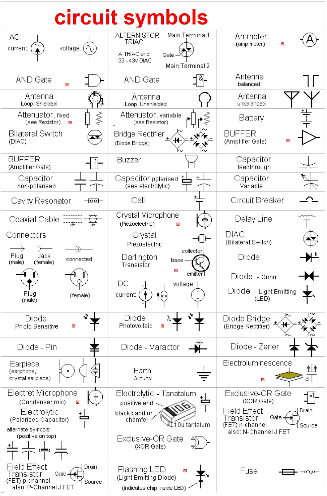
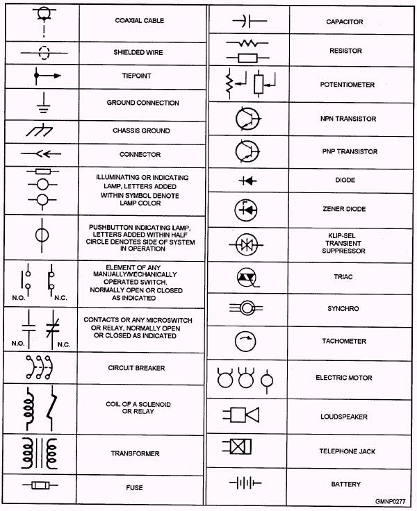
Electrical symbols are standardized graphical representations of electrical components and their functions within a circuit. A collection of these symbols arranged to illustrate a circuit's structure is often called an electrical schematic, wiring diagram, or simply a circuit diagram. Whether you're a seasoned engineer or just starting to explore the world of electronics, understanding these symbols is crucial.
From the simplest resistor to the most complex microchip, every electrical component has its unique symbolic representation. These symbols, organized and presented on a chart, an electrical symbols chart or diagram, provide a visual shorthand that transcends language barriers. They enable engineers to design, analyze, and troubleshoot electrical systems with efficiency and accuracy.
The history of electrical symbols is intertwined with the development of electricity itself. As electrical technologies evolved, so too did the need for a standardized way to represent circuits. Early electrical diagrams often used realistic depictions of components, but these proved cumbersome and inefficient. Over time, simplified, abstract symbols emerged, paving the way for the standardized charts we use today.
The standardization of electrical diagrams is crucial for collaboration and safety. Imagine the chaos if every engineer used their own set of symbols! Standardized electrical symbol dictionaries, whether in chart or digital format, ensure that everyone is speaking the same language, reducing the risk of misinterpretations and errors that could lead to faulty designs or even dangerous electrical hazards.
A resistor, represented by a zig-zag line, limits the flow of current. A capacitor, symbolized by two parallel lines, stores electrical energy. A diode, shown as a triangle with a line, allows current to flow in only one direction. These are just a few examples of the hundreds of symbols used in electrical diagrams.
Understanding a reference of electrical symbols offers several advantages. Firstly, it facilitates clear communication among engineers, technicians, and electricians. Secondly, it simplifies complex circuit designs, making them easier to analyze and troubleshoot. Thirdly, using standardized symbols ensures safety and reduces the risk of errors during circuit construction and maintenance.
One practical application of an electrical symbol identification chart is in home wiring projects. Before rewiring a light fixture, you can consult a chart to identify the symbols for switches, wires, and the fixture itself, enabling you to understand the existing wiring and plan your modifications safely. Similarly, if you're troubleshooting a faulty appliance, understanding the symbols on its circuit diagram can help you pinpoint the problem component.
When working with an electrical circuit drawing guide, ensure the chart you’re using adheres to the relevant standards (e.g., IEC, ANSI, IEEE). Familiarize yourself with the most common symbols, like those for resistors, capacitors, and diodes. Refer to the chart whenever you encounter an unfamiliar symbol.
Advantages and Disadvantages of Using Standardized Electrical Symbol Charts
| Advantages | Disadvantages |
|---|---|
| Clear communication | Requires learning and memorization |
| Simplified circuit analysis | Can be overwhelming for beginners due to the sheer number of symbols |
| Enhanced safety | Different standards might use slightly different symbols for the same component, potentially causing confusion. |
Best Practice: Always double-check the standard used in the electrical symbols index you’re referencing.
Real-world examples include the use of electrical symbol tables in automotive wiring diagrams, building blueprints, and industrial control systems.
A common challenge is keeping up with the evolving set of symbols for newer technologies. The solution is to consult updated industry standards and online resources.
FAQ: What does the ground symbol look like? Answer: It typically resembles three horizontal lines decreasing in length.
Tip: Use flashcards or online quizzes to memorize electrical symbols effectively.
In conclusion, electrical symbols, often presented in charts or tables, are fundamental to the world of electrical engineering and electronics. Their standardized nature facilitates clear communication, simplifies complex designs, and promotes safety. While the sheer number of symbols can seem daunting at first, understanding their importance and utilizing resources like online dictionaries and industry standards empowers anyone working with electrical circuits. From designing complex industrial systems to troubleshooting a simple household appliance, the ability to interpret electrical symbols is a valuable skill. Embrace these visual cues, and unlock the power to navigate the intricate world of electricity.
Silence your space diy sound baffle noise reduction guide
Power up your world the ultimate guide to transformer ac to dc converters
Decoding medicare supplemental insurance navigate the healthcare maze


