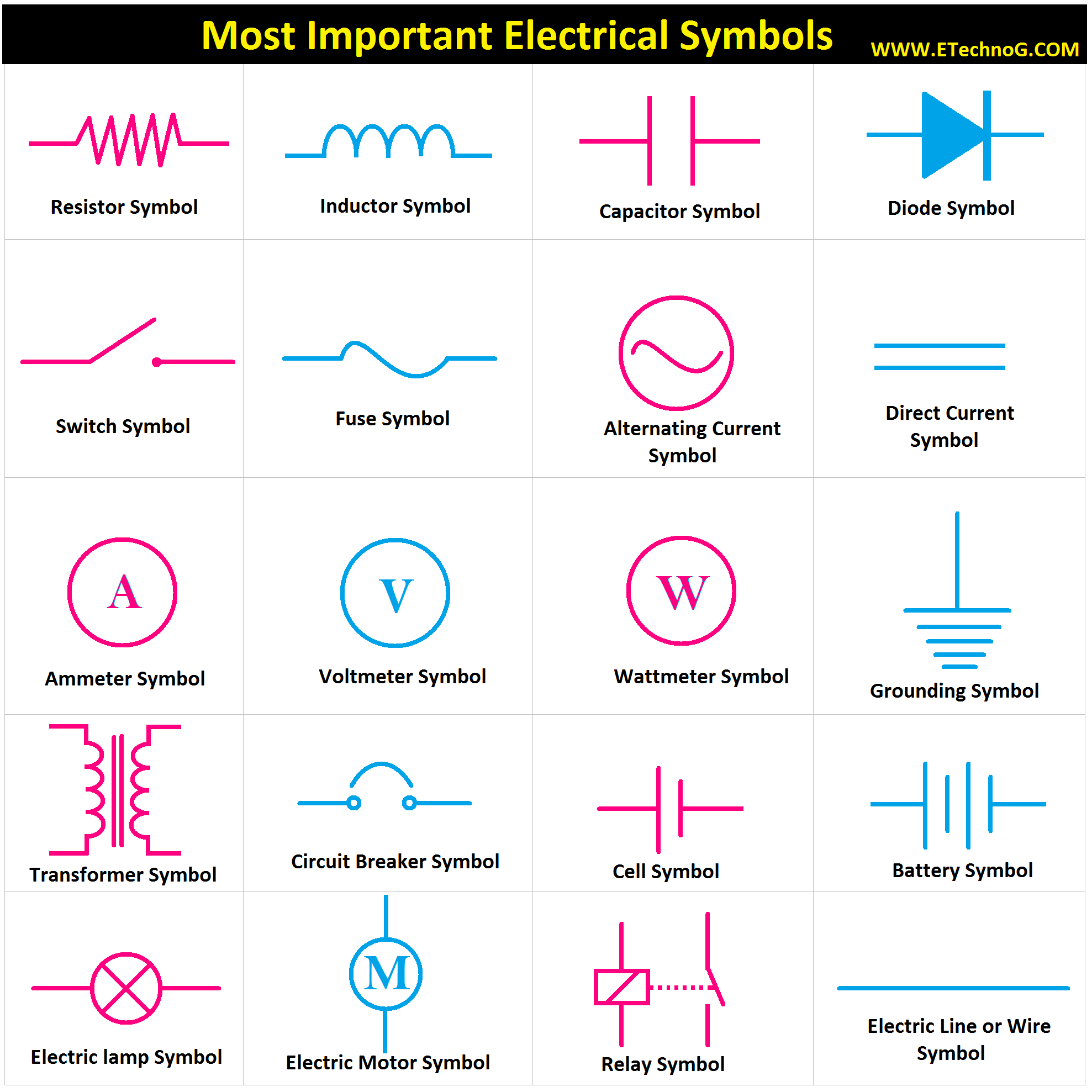
Decoding Electrical Symbols: A Comprehensive Guide

Have you ever looked at an electrical diagram and felt a wave of bewilderment wash over you? Those strange squiggles and circles might seem like a secret code, but they're actually a crucial language for anyone working with electricity. Understanding what an electrical symbol represents unlocks the world of circuit design and allows us to communicate complex electrical concepts clearly and efficiently.
So, what is an electrical symbol? In simple terms, it's a graphical representation of an electrical component or function. Think of it as a shorthand notation that engineers, electricians, and hobbyists use to convey information about a circuit without writing lengthy descriptions. These symbols are standardized, making them universally understood across different countries and industries.
Imagine trying to describe a complex circuit using only words. It would be a tedious and confusing process. Electrical symbols provide a visual language that simplifies this process dramatically. They allow us to quickly grasp the overall layout of a circuit, identify its components, and understand how they interact with each other.
The history of electrical symbols is intertwined with the development of electricity itself. As new electrical components were invented, the need for a standardized way to represent them arose. Over time, various organizations, such as the International Electrotechnical Commission (IEC), have played a key role in establishing and maintaining these standards. This standardization is crucial for ensuring clear communication and preventing misunderstandings in electrical projects.
The importance of understanding electrical symbols cannot be overstated. Whether you're a professional electrician designing complex wiring systems or a DIY enthusiast tackling a home improvement project, knowing these symbols is essential for safety and efficiency. Misinterpreting a symbol could lead to faulty circuits, damaged equipment, or even electrical hazards. So, taking the time to learn these symbols is a worthwhile investment.
For example, a straight line often represents a wire, while a zigzag line signifies a resistor. A circle with a plus and minus sign inside denotes a battery. These simple yet powerful symbols allow us to visualize the flow of electricity within a circuit and understand how different components contribute to its overall function.
One of the key benefits of using electrical symbols is their conciseness. They allow for complex circuits to be represented in a compact and easily understandable format. This is particularly helpful in large-scale projects where detailed diagrams are essential for planning and execution.
Another benefit is clarity. Electrical symbols eliminate ambiguity and ensure that everyone involved in a project is on the same page. This is crucial for preventing errors and ensuring that the final product meets the required specifications.
Finally, electrical symbols facilitate communication. They provide a universal language that transcends linguistic barriers, allowing engineers and technicians from different parts of the world to collaborate effectively.
If you're new to electrical diagrams, a great way to start learning is by focusing on the most common symbols. Create flashcards, practice drawing them, and try to identify them in simple circuit diagrams. Online resources and textbooks can be invaluable tools in this learning process.
Advantages and Disadvantages of Standardized Electrical Symbols
| Advantages | Disadvantages |
|---|---|
| Clear communication | Requires initial learning |
| International standardization | Can be complex for very specialized components |
| Simplified representation of complex circuits | Subject to occasional revisions and updates |
Best practice is to consult updated resources like the IEC standards for the most accurate representations.
Examples of symbols include the resistor, capacitor, diode, transistor, and switch, each with unique representations.
A challenge can be keeping up with new symbols for emerging technologies, but online databases and industry publications offer solutions.
FAQ: What is a resistor symbol? What is a capacitor symbol? What is a diode symbol? What is the symbol for a ground connection? What is the symbol for AC power? What is the symbol for a switch? What is the symbol for a transformer? What is the symbol for a battery?
General answers to the FAQ point to the specific graphical representation of each component and their function in a circuit.
A helpful tip is to use software tools that provide libraries of electrical symbols to simplify circuit design.
In conclusion, understanding electrical symbols is fundamental to anyone working with electrical systems. These concise, standardized representations not only simplify complex circuits but also facilitate clear communication among professionals. From the simplest resistor to the most intricate integrated circuit, every symbol plays a vital role in conveying critical information. By learning and applying these symbols correctly, we ensure the safety, efficiency, and successful operation of electrical systems. So, take the plunge and delve into the fascinating world of electrical symbols – it’s a journey that will empower you to navigate the language of electricity with confidence and precision. Begin your exploration today by researching online resources, checking out library books, or even enrolling in a basic electronics course. The knowledge you gain will be a valuable asset in any electrical endeavor.
The subtle dance of liqueur alcohol content
The art of hauling exploring the jeep grand cherokee towing experience
Kids name tattoos a thoughtful exploration


